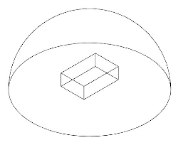
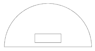
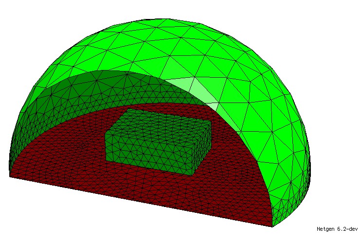
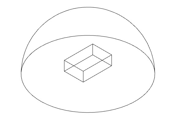
Hello, I am trying to model a simple 3D electrostatics problem. A metallic object at 1 Volt is surrounded by air and is positioned above a ground plane. The upper part of the dome is a “distant surface” air boundary. My objective is to obtain a result containing the surface charge density at each mesh node on the surface of the energized object. A .step CAD file is attached (dome.step). Since I don’t care about anything internal to the cuboid, the volume consists of a dome with a cuboid void. https://ngsolve.org/media/kunena/attachments/1333/dome.zip
I normally use the netgen gui to mesh and export to Elmer Format. However, I learned that this could be done in ngsolve with scripting.
I have been able to get as far importing the .step file and meshing the object (code below). The imported step file has surfaces: 1 = air boundary, 2 = ground plane, 3 through 8 = cuboid.
Could someone point me in the right direction or give example scripts that show:
[ol]
[li] How to name boundaries (I would like to set the air boundary to bc 1, ground plane to bc 2, and energized surfaces to bc 3.[/li]
[li] How to assign potentials to a bc [/li]
[li] How to assign a Nuemann boundary condition to the air boundary[/li]
[li] How to solve and get an output with the charge density at the surface nodes of the energized cuboid [/li]
[/ol]
I’m really stuck on the first item. I might be able to find the other three if I can get that one figured out, but if the others are quick for someone to point out, I would really appreciate the assistance. Thanks!
.
.
from netgen.occ import *

geo = OCCGeometry('C:/Temp/dome.step') #import step file

for x in range(2,8):  #iterate through surfaces of cuboid
    geo.SetFaceMeshsize(x,25)  #set mesh size for cuboid surfaces

geo.SetFaceMeshsize(0,100)  #set mesh size for air boundary
geo.SetFaceMeshsize(1,25)  #set mesh size for ground plane
mesh = geo.GenerateMesh(maxh = 100,grading = 0.75)  #mesh the volume with prescribed size and grading

mesh.Save('C:/Temp/dome.vol') #save mesh out
For setting non-homogeneous Dirichlet boundary conditions I recommend this tutorial and this.
Neumann boundary conditions should be straight-forward with 2). For homogeneous Neumann conditions you mostly have the “do-nothing” conditions, otherwise it goes naturally into the right-hand side of your problem.
The tutorials in 2) should be a good starting point here.
[ol]
[li]Per your suggestion I ran the code with the SetBCName function applied as shown below. The code runs fine (no errors), but when I explore the mesh boundary conditions in the netgen gui, all boundaries have the name ‘voltage’ (no ‘air’ and ‘ground’ boundaries). Face index 1 and 2 should be ‘air’ and ‘ground’ respectively. Suggestions?[/li]
[li]Also, how do I assign a face index to a bc property? In this case I need face index 1 to be bc property 1, face index 2 to be bc property 2, and face indices 3 through 8 to be bc property 3.[/li]
[/ol]
from netgen.occ import *
from ngsolve import *

geo = OCCGeometry('C:/00_Temp/netgen testing/dome.step')


for x in range(2,8):
    geo.SetFaceMeshsize(x,100)

geo.SetFaceMeshsize(0,1000)
geo.SetFaceMeshsize(1,250)
mesh = geo.GenerateMesh(maxh = 1000,grading = 0.75)

mesh.SetBCName(0,'air')
mesh.SetBCName(1,'ground')

for x in range(2,8):
    mesh.SetBCName(x,'voltage')

mesh.Save('C:/00_Temp/netgen testing/dome.vol')
with the attached code I get also air and ground as boundaries
Output:
boundaries = (‘air’, ‘ground’, ‘voltage’, ‘voltage’, ‘voltage’, ‘voltage’, ‘voltage’, ‘voltage’)
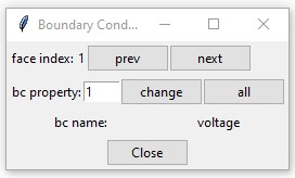
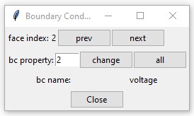
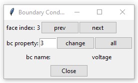
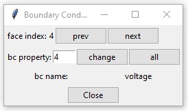
I noticed that the .vol mesh file saved after naming the boundaries does not seem to properly retain the data. When I open the .vol file manually with the netgen gui then go to mesh=>edit boundary conditions, all the boundary names say ‘voltage’. If I move the ngmesh.SetBCName(1,'ground') line so that it is the last of the boundary naming entries then all boundaries show up as “ground”. Is this a bug?
Ultimately I am trying to export the mesh to an elmerfem format then user elmer to solve the electrostatics problem and get a result that contains all the node x,y,z locations and surface density values at each node. Perhaps it would be easier to do all that from within ngsolve?
I was wondering if you still have access to this dome.py file or you remember how to do this, as it would be very helpful for my current project. Thanks!