How to interpret bending moment components?

I have this code to solve for the deflection, moments, and shear forces in a square plate with two edges (horizontal) simply-supported (soft) and two remaining (vertical) free.

from ngsolve import *
from ngsolve.webgui import Draw
mesh = Mesh (unit_square.GenerateMesh(maxh=0.05))

order = 2
Sigma = HDivDiv(mesh, order=order,  dirichlet="left|right|bottom|top", plus=True)  
W = H1(mesh, order=order+1, dirichlet="bottom|top")  
V = HCurl(mesh, order=order)
X = Sigma * W * V

t = 1.0/50 # thickness

sigma, w, beta = X.TrialFunction()
tau, v, delta = X.TestFunction()

n = specialcf.normal(2)
def tang(u): return u-(u*n)*n
    
def DivDiv(sigma,delta): 
    return div(sigma)*delta*dx - (sigma*n)*tang(delta)*dx(element_boundary=True)

a = BilinearForm(InnerProduct(sigma,tau)*dx + DivDiv(sigma,delta) + DivDiv(tau,beta) \
                 - 1/t**2 * (grad(w)-beta)*(grad(v)-delta)*dx).Assemble()
f = LinearForm(200*v*dx).Assemble()

gfu = GridFunction(X)
gfu.vec.data = a.mat.Inverse(X.FreeDofs(), inverse="sparsecholesky") * f.vec

gfsigma, gfw, gfbeta = gfu.components

print ("vertical displacement")
Draw (gfw, deformation=True)
print ("rotation vector beta")
Draw (gfbeta, vectors= { "grid_size" : 40 } )
print ("bending moment_xx")
Draw (gfsigma[0,0], mesh);
print ("bending moment_yy")
Draw (gfsigma[1,1], mesh);
print ("twisting moment")
Draw (gfsigma[1,0], mesh);

The code is a tweak of one of the tutorials. The solution is a bit peculiar – I don’t trust it. The deflection should really look like this (on one quarter of the plate):
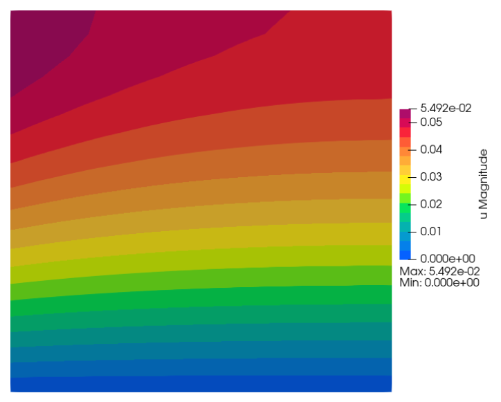
But what I totally don’t understand is how to plot the bending moment components: am I doing it right? What is the logic? m_yy looks reasonable (even if not correct), but I don’t get anything useful from the other components – they are all zero!? Or, perhaps it all goes with the solution not being quite right, and I did get the correct way of referring to the moment components?

Thanks :slight_smile:

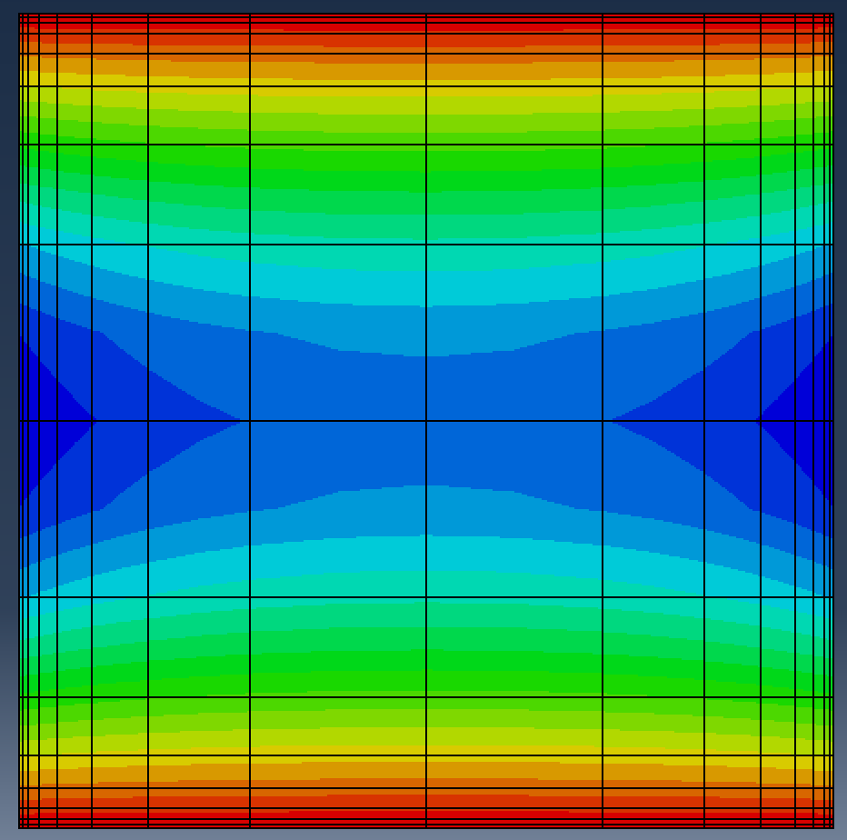
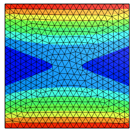
This is deflection on the full square plate:

The above is the magnitude, this is the signed component (negative in the middle).

It would seem there was something funny with the tutorial code I copied. With this code things are working as expected:

from ngsolve import *
from netgen.occ import *
from ngsolve.webgui import Draw

L = 1.0
thickness = 0.02
E, nu, k = 10.92, 0.3, 5 / 6
G = E / (2 * (1 + nu))
fz = -100
order = 2


def DMat(mat, E, nu):
    return E / (12 * (1 - nu**2)) * ((1 - nu) * mat + nu * Trace(mat) * Id(2))


def DMatInv(mat, E, nu):
    return (
        12
        * (1 - nu**2)
        / E
        * (1 / (1 - nu) * mat - nu / (1 - nu**2) * Trace(mat) * Id(2))
    )


mesh = Mesh(unit_square.GenerateMesh(maxh=0.05))

fesB = HCurl(mesh, order=order - 1)
fesS = HDivDiv(mesh, order=order - 1, dirichlet=".*")
fesW = H1(mesh, order=order, dirichlet="bottom|top")

fes = fesW * fesB * fesS
(w, beta, sigma), (v, delta, tau) = fes.TnT()

n = specialcf.normal(2)

a = BilinearForm(fes, symmetric=True)
# bending part
a += (
    -InnerProduct(DMatInv(sigma, E, nu), tau)
    + InnerProduct(tau, Grad(beta))
    + InnerProduct(sigma, Grad(delta))
) * dx
a += -(sigma[n, n] * delta * n + tau[n, n] * beta * n) * dx(element_boundary=True)
# shearing part
a += k * G / thickness**2 * InnerProduct(Grad(w) - beta, Grad(v) - delta) * dx
a.Assemble()

f = LinearForm(fz * v * dx).Assemble()

gf_solution = GridFunction(fes)
gf_w, gf_beta, gf_sigma = gf_solution.components

inv = a.mat.Inverse(fes.FreeDofs(), inverse="")
gf_solution.vec.data = inv * f.vec

Draw(gf_w, mesh, "w")
print ("bending moment_xx")
Draw (gf_sigma[0,0], mesh);
print ("bending moment_yy")
Draw (gf_sigma[1,1], mesh);
print ("twisting moment")
Draw (gf_sigma[1,0], mesh);
q = k * G / thickness**2 * (Grad(gf_w) - gf_beta)
print('shear force x')
Draw(q[0], mesh)
print('shear force y')
Draw(q[1], mesh)

But: I could use some hints as to the design of the mesh to have a boundary layer. I am mostly interested in the shear forces. So I want a strong refinement towards the edges. Anything will help…

Thanks.

In case anyone is interested, here is the code with graded mesh:

from ngsolve import *
from netgen.occ import *
from ngsolve.webgui import Draw

L = 1.0
thickness = 0.02
E, nu, k = 10.92, 0.3, 5 / 6
G = E / (2 * (1 + nu))
fz = -100
order = 4

def DMat(mat, E, nu):
    return E / (12 * (1 - nu**2)) * ((1 - nu) * mat + nu * Trace(mat) * Id(2))

def DMatInv(mat, E, nu):
    return (
        12
        * (1 - nu**2)
        / E
        * (1 / (1 - nu) * mat - nu / (1 - nu**2) * Trace(mat) * Id(2))
    )

shape = Rectangle(1,1).Face()
shape.edges.hpref = 1
shape.vertices.hpref = 1

shape.edges.Max(X).name="right"
shape.edges.Min(X).name="left"
shape.edges.Max(Y).name="top"
shape.edges.Min(Y).name="bottom"
mesh = shape.GenerateMesh(maxh=0.05, dim=2)
# mesh = Mesh(unit_square.GenerateMesh(maxh=0.05))
mesh.RefineHP(3,0.3)
Draw (mesh)

fesB = HCurl(mesh, order=order - 1)
fesS = HDivDiv(mesh, order=order - 1, dirichlet=".*")
fesW = H1(mesh, order=order, dirichlet="bottom|top")

fes = fesW * fesB * fesS
(w, beta, sigma), (v, delta, tau) = fes.TnT()

n = specialcf.normal(2)

a = BilinearForm(fes, symmetric=True)
a += (
    -InnerProduct(DMatInv(sigma, E, nu), tau)
    + InnerProduct(tau, Grad(beta))
    + InnerProduct(sigma, Grad(delta))
) * dx
a += -(sigma[n, n] * delta * n + tau[n, n] * beta * n) * dx(element_boundary=True)
a += k * G / thickness**2 * InnerProduct(Grad(w) - beta, Grad(v) - delta) * dx
a.Assemble()

f = LinearForm(fz * v * dx).Assemble()

gf_solution = GridFunction(fes)
gf_w, gf_beta, gf_sigma = gf_solution.components

inv = a.mat.Inverse(fes.FreeDofs(), inverse="")
gf_solution.vec.data = inv * f.vec

Draw(gf_w, mesh, "w")
print ("bending moment_xx")

Draw (gf_sigma[0,0], mesh);
print ("bending moment_yy")
Draw (gf_sigma[1,1], mesh);
print ("twisting moment")
Draw (gf_sigma[1,0], mesh);

q = k * G / thickness**2 * (Grad(gf_w) - gf_beta)
print('shear force x')
Draw(q[0], mesh)
print('shear force y')
Draw(q[1], mesh)

you were missing the material law in the frist version where you copied the code from the tutorial - so this calculates the nu == 0 case, here a fixed version:

from ngsolve import *
mesh = Mesh (unit_square.GenerateMesh(maxh=0.05))

order = 2
Sigma = HDivDiv(mesh, order=order,  dirichlet="left|right|bottom|top", plus=True)  
W = H1(mesh, order=order+1, dirichlet="bottom|top")  
V = HCurl(mesh, order=order)
X = Sigma * W * V

t = 1.0/50 # thickness
E, nu, k = 10.92, 0.3, 5/6  # E/(12*(1-nu**2)) == 1, i.e. unit bending stiffness
G = E/(2*(1+nu))

def DMatInv(mat):
    return 12*(1-nu**2)/E * (1/(1-nu)*mat - nu/(1-nu**2)*Trace(mat)*Id(2))

sigma, w, beta = X.TrialFunction()
tau, v, delta = X.TestFunction()

n = specialcf.normal(2)
def tang(u): return u-(u*n)*n

def DivDiv(sigma,delta):
    return div(sigma)*delta*dx - (sigma*n)*tang(delta)*dx(element_boundary=True)

a = BilinearForm(InnerProduct(DMatInv(sigma),tau)*dx + DivDiv(sigma,delta) + DivDiv(tau,beta) \
                 - k*G/t**2 * (grad(w)-beta)*(grad(v)-delta)*dx).Assemble()
f = LinearForm(200*v*dx).Assemble()

gfu = GridFunction(X)
gfu.vec.data = a.mat.Inverse(X.FreeDofs(), inverse="sparsecholesky") * f.vec

gfsigma, gfw, gfbeta = gfu.components

print ("vertical displacement")
Draw (gfw, name="gfw", deformation=True)
print ("rotation vector beta")
Draw (gfbeta, name="gfbeta", vectors= { "grid_size" : 40 } )
print ("bending moment_xx")
Draw (gfsigma[0,0], mesh, name="gfsigma00");
print ("bending moment_yy")
Draw (gfsigma[1,1], mesh, name="gfsigma11");
print ("twisting moment")
Draw (gfsigma[1,0], mesh, name="gfsigma01");

Edit: Ah sorry just now understood this was exactly the point of your second message :wink:

1 Like

Ah and refinement towards the edges you can get using RefineHP:

CCGeometry

shape = unit_square.shape
shape.vertices.hpref = 2
shape.edges.hpref = 2
mesh = Mesh(OCCGeometry(shape, dim=2).GenerateMesh(maxh=0.1))
mesh.RefineHP(2, factor=0.35)
Draw(mesh)
1 Like