Hi,
I’ve solved the Team 7 problem from TEAM Problems – International Compumag Society
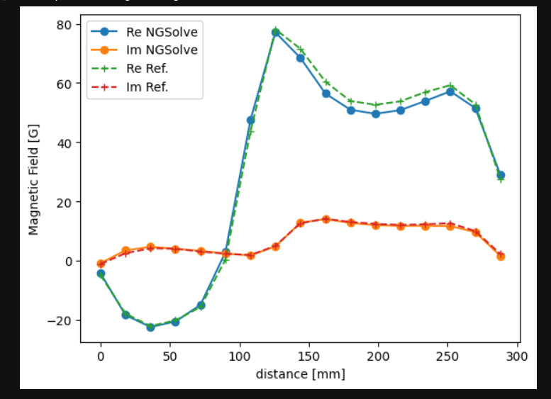
The comparison between NGSolve and the reference value along a line is plotted below. There is a slight discrepancy, especially for the real part near x=200 mm. Anyone that have a suggestion on how to improve my implementation and the mesh?
team7.ipynb (68.2 KB)
Haven’t tried, but from your code it looks like you defined the current path not following the coil. That would be my first guess
Thanks!
I think that I’ve fixed the coil current now. Here is my change where the b1-b4 are the straight parts of the coil:
tau = CoefficientFunction(((y_coil-y), -(x_coil-x), 0)) # anti-clock-wise direction
tau = 1.0/Norm(tau)*tau
I0 = 2742
j = I0/(h_coil*t_coil) # Ampere/m^2 (+ for anticlockwise and - for clockwise direction)
f = LinearForm(fes)
f += SymbolicLFI(j*tau*v, definedon=mesh.Materials("coilbend"))
f += SymbolicLFI(CoefficientFunction((0,j,0))*v, definedon=mesh.Materials("b1"))
f += SymbolicLFI(CoefficientFunction((-j,0,0))*v, definedon=mesh.Materials("b2"))
f += SymbolicLFI(CoefficientFunction((0,-j,0))*v, definedon=mesh.Materials("b3"))
f += SymbolicLFI(CoefficientFunction((j,0,0))*v, definedon=mesh.Materials("b4"))
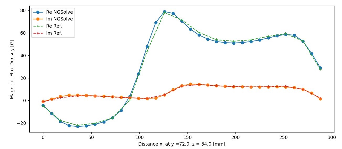
The comparison looks like this now:
I have added comparisons along one more line in the attached notebook, and also for the induced current in the plate along two lines
team7.ipynb (701.2 KB)
.
1 Like